Both
DRC and optimization constraints follow environmental constraints. Setting up
of operating conditions and wire load model falls under environmental
constraints.
The constraints are:
- set_operating_conditions
This
constraint describes PVT condition of the design. Names of the operating
condition is dependent on library. Generally worst corner library is used for
synthesis.
set_operating_conditions
[-library lib_name] [-analysis_type type] [-max max_condition] [-min min_condition] [-max_library max_lib] [-min_library min_lib] [-object_list objects] [condition]
#
Sets the specified operating condition for timing analysis. Analysis type can
be single, bc_wc, or on_chip_variation. Operating conditions are
defined in libraries using the operating_conditions command.
Examples:
set_operating_conditions
-analysis_type bc_wc
set_operating_conditions
WCCOM
set_operating_conditions
-analysis_type on_chip_variation
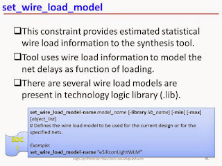
- set_wire_load_model
This
constraint provides estimated statistical wire load information to the
synthesis tool. Tool uses wire load information to model the net delays as
function of loading. There are seveal wire load models are present in
technology logic library (.lib).
set_wire_load_model
-name model_name [-library lib_name] [-min] [-max] [object_list]
#
Defines the wire load model to be used for the current design or for the
specified nets.
Example:
set_wire_load_model
-name “eSiliconLightWLM”
- set_wire_load_mode
This constraints defines any of the three modes associated
with wire load models. The three modes are top, segmented and enclosed.
set_wire_load_mode
mode_name
#
Defines the mechanism of how a wire load model is to be used for nets in a
hierarchical design. The mode_name can be top, enclosed, or segmented. The top mode causes the wire load
model defined in the top-level of the hierarchy to be used at all lower levels.
The enclosed
mode
causes the wire load odel of the block that fully encloses that net to be used
for that net. The segmented
mode
causes net segment in the block to use the block’s wire load model.
Example:
set_wire_load_mode
enclosed
- set_drive
This constraints specifies the
drive strength of input port.
set_drive
[-rise] [-fall] [-min] [-max] resistance
port_list
# Is
used to specify the drive strength of the input port. It specifies the external
drive resistance to the port. A value of 0 signifies highest drive strength.
Example:
set_drive
0
{CLK RST}
- set_driving_cell
This constraints
specifies the external drive strangth of input port.
set_driving_cell
[-lib_cell lib_cell_name] [-rise] [-fall] [-library lib_name] [-pin pin_name] [-from_pin from_pin_name] [-multiply_by factor] [-dont_scale] [-no_design_rule] [-input_transition_rise
rise_time] [-input_transition_fall
fall_time] [-min] [-max] [-clock clock_name] [-clock_fall] port_list
# Is
used to model the drive resistance of the cell driving the input port.
Example:
set_driving_cell
-lib_cell BUFX4 -pin ZN [all_inputs]
- set_load
This constraint defines the
capacitive load to the output port or any specified net.
set_load
[-min] [-max] [-subtract_pin_load] [-pin_load] [-wire_load] value objects
#
Set the value of capacitive load on pin or net in design. The -subtract_pin_load
option
specifies to subtract the pin cap from the indicated load.
Examples:
set_load
50 [all_outputs]
set_load
0.1
[get_pins UFF0/Q] # On an internal pin.
set_load
-subtract_pin_load 0.025 [get_nets UCNT0/NET5]
# On
a net.
- set_fanout_load
set_fanout_load
value
port_list
#
Sets the specified fanout load on the output ports.
Example:
set_fanout_load
5 [all_outputs]
- set_input_transition
set_input_transition
[-rise] [-fall] [-min] [-max] [-clock clock_name] [-clock_fall] transition
port_list
#
Specifies the transition time on an input pin.
Examples:
set_input_transition
0.2
[get_ports
SD_DIN*]
set_input_transition
-rise 0.5 [get_ports GPIO*]
Sign up here with your email


ConversionConversion EmoticonEmoticon