This game test reaction time of two players, and declare the fastest one as winner. To do this I am using external interrupts and pin change interrupts in atmega328p. It gives four chance to each play, time of each chance is summed up and then player with minimum time is declared as the winner.
For the demo purpose, I’ll be using pseudo random function in it, just to keep track.
This game has precision of 1ms and accuracy of about +/- 4ms.
It also displays the concept of debouncing.
This game’s main motive is to show the beauty of external interrupts over polling and to show the how to reduce debouncing effect using software modifications.
f = <source_code’s_file_name>
h = <header_file_name>
avr-gcc -g -mmcu=atmega328p -Wall -Os $(h).c $(f).c -o $(f).elf
avr-objcopy -j .text -j .data -O ihex $(f).elf $(f).hex
sudo avrdude -F -V -c arduino -p m328p -P /dev/ttyUSB* -b 57600 -e -U flash:w:$(f).hex
Just type these four commands, in the same order, in your terminal and remember to put the source code’s filename in variable “f” and header filename in variable “h”. These command are for Linux users only.
First command stores the filename in variable “f”, second command is used to convert source code to .elf file, third command is used to convert that .elf file to .hex file which can be uploaded on atmega328p, fourth command is used to upload that .hex file.
External interrupts are very useful to interact with physical world, because of its unpredictable nature.
There are two ways of sensing data from different pins, one is polling other is using interrupts. Both polling and interrupts have pros and cons associated with them.
In polling you check status of each and every pin in a sequential manner:
pros:
1) Everyone one gets a fair chance
cons:
1) Inefficient, can’t do some other activity in between, specially have to go and check
2) Loss of data might occur in an unpredictable scenario.
Whereas, in interrupts you let your microcontroller do some other important stuff and whenever an interrupt is generated you stop the normal working of microcontroller and change its behavior accordingly.
pros:
1) Efficient, can do some other work in between
2) No loss of data
cons:
1) Extra resources on hardware level are required

• Bit 7..4 – Res: Reserved Bits
These bits are unused bits in the ATmega48PA/88PA/168PA/328P, and will always read as zero.
• Bit 3, 2 – ISC11, ISC10: Interrupt Sense Control 1 Bit 1 and Bit 0
Used for Interrupt 1 Sense Control, check the table below
• Bit 1, 0 – ISC01, ISC00: Interrupt Sense Control 0 Bit 1 and Bit 0
Used for Interrupt 0 Sense Control, check the table below

Bit 7:2 – Reserved
These bits are unused bits in the ATmega48A/PA/88A/PA/168A/PA/328/P, and will always read as zero.
• Bit 1 – INT1: External Interrupt Request 1 Enable
When the INT1 bit is set (one) and the I-bit in the Status Register (SREG) is set (one), the external pin interrupt is enabled.
• Bit 0 – INT0: External Interrupt Request 0 Enable
When the INT0 bit is set (one) and the I-bit in the Status Register (SREG) is set (one), the external pin interrupt is enabled.

Bit 7:3 – Reserved
These bits are unused bits in the ATmega48A/PA/88A/PA/168A/PA/328/P, and will always read as zero.
• Bit 2 – PCIE2: Pin Change Interrupt Enable 2
When the PCIE2 bit is set (one) and the I-bit in the Status Register (SREG) is set (one), pin change interrupt 2 is enabled. Any change on any enabled PCINT[23:16] pin will cause an interrupt.
• Bit 1 – PCIE1: Pin Change Interrupt Enable 1
When the PCIE1 bit is set (one) and the I-bit in the Status Register (SREG) is set (one), pin change interrupt 1 is enabled. Any change on any enabled PCINT[14:8] pin will cause an interrupt.
• Bit 0 – PCIE0: Pin Change Interrupt Enable 0
When the PCIE0 bit is set (one) and the I-bit in the Status Register (SREG) is set (one), pin change interrupt 0 is enabled. Any change on any enabled PCINT[7:0] pin will cause an interrupt.
Bit 7 – Reserved
This bit is an unused bit in the ATmega48A/PA/88A/PA/168A/PA/328/P, and will always read as zero.
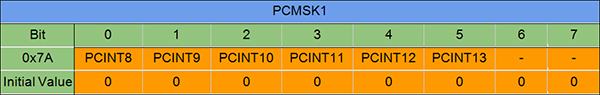
• Bit 6:0 – PCINT[14:8]: Pin Change Enable Mask 14...8
Each PCINT[14:8]-bit selects whether pin change interrupt is enabled on the corresponding I/O pin. If PCINT[14:8] is set and the PCIE1 bit in PCICR is set, pin change interrupt is enabled on the corresponding I/O pin. If PCINT[14:8] is cleared, pin change interrupt on the corresponding I/O pin is disabled.
Sign up here with your email
ConversionConversion EmoticonEmoticon